
Rotational Molding: A Complete Guide to the Process
Rotational molding (rotomolding) is a low-pressure plastics process that makes hollow, one-piece parts. Powdered resin, usually polyethylene, is loaded into a hollow metal mold, which is heated while it rotates slowly on two axes. The melting powder coats the inside of the mold, then cools into a single piece with even walls and low internal stress.
The process fits large hollow parts made at low to mid volumes, such as tanks, housings, liners, bins and enclosures, in runs from a few dozen to a few thousand parts a year. Small, thin-walled parts with tight tolerances and high annual volumes usually belong in injection or blow molding.
TL;DR
- Rotational molding heats powdered plastic inside a closed mold rotating on two axes, with no molding pressure.
- Each cycle runs through four stages: charging, heating and fusion, cooling, and demolding.
- The lack of pressure explains the process: low-cost molds, low residual stress, even walls into the corners, very large parts, and long cycle times.
- Polyethylene makes up the large majority of rotomolded parts, with LLDPE as the default grade.
- Rotomolding suits large hollow parts at low to mid volume, while blow and injection molding take over at high volume and thermoforming handles open shells.
- Decide the process on engineering grounds before the design is locked, testing the part against size, volume, wall thickness, tolerance and detail.
Rotational molding can produce a hollow part taller than the engineer who specified it, with brass threads molded into the wall. That range makes it tempting to specify, and it is also why so many rotomolded programs run into trouble.
The most expensive mistake in custom plastic parts is the late process decision. A part gets designed around injection molding, goes out for rotomolding quotes when the injection tooling estimate comes back, and arrives with wall sections, tolerances and features that conflict with how rotomolding works. The fix is to choose the process at the start of a program, on the physics of each process, while the geometry can still change.
What is rotational molding?
Rotational molding is a thermoplastic process that forms hollow parts by tumbling powdered resin inside a heated, rotating mold. Heat melts the powder onto the mold wall, rotation carries it over every surface, and cooling sets the part. Rotomolding and rotomoulding (the British spelling) name the same process, which became an industrial plastics process once polyethylene powders were widely available in the 1960s.
Defined Term: Rotational molding
a low-pressure thermoplastic process in which a measured charge of powdered resin is heated inside a closed mold rotating on two perpendicular axes, so the melt coats the mold interior and forms a hollow, one-piece part.
Three characteristics set it apart from other ways of making hollow or large plastic parts:
- No molding pressure. Gravity and rotation bring the powder to the wall, and heat conducted through the mold does the rest.
- Powder in, hollow shell out. Resin is ground to about 35 mesh (roughly 500 microns) and forms a closed or nearly closed shell.
- Heat-limited cycles. Heat has to move through the mold wall and the plastic, so cycles run in tens of minutes.
How does rotational molding work?
Every rotational molding cycle runs through four stages: charging, heating and fusion, cooling, and demolding. The mold keeps rotating on two perpendicular axes through heating and cooling, which spreads the resin evenly and keeps the melt from sagging before it sets.
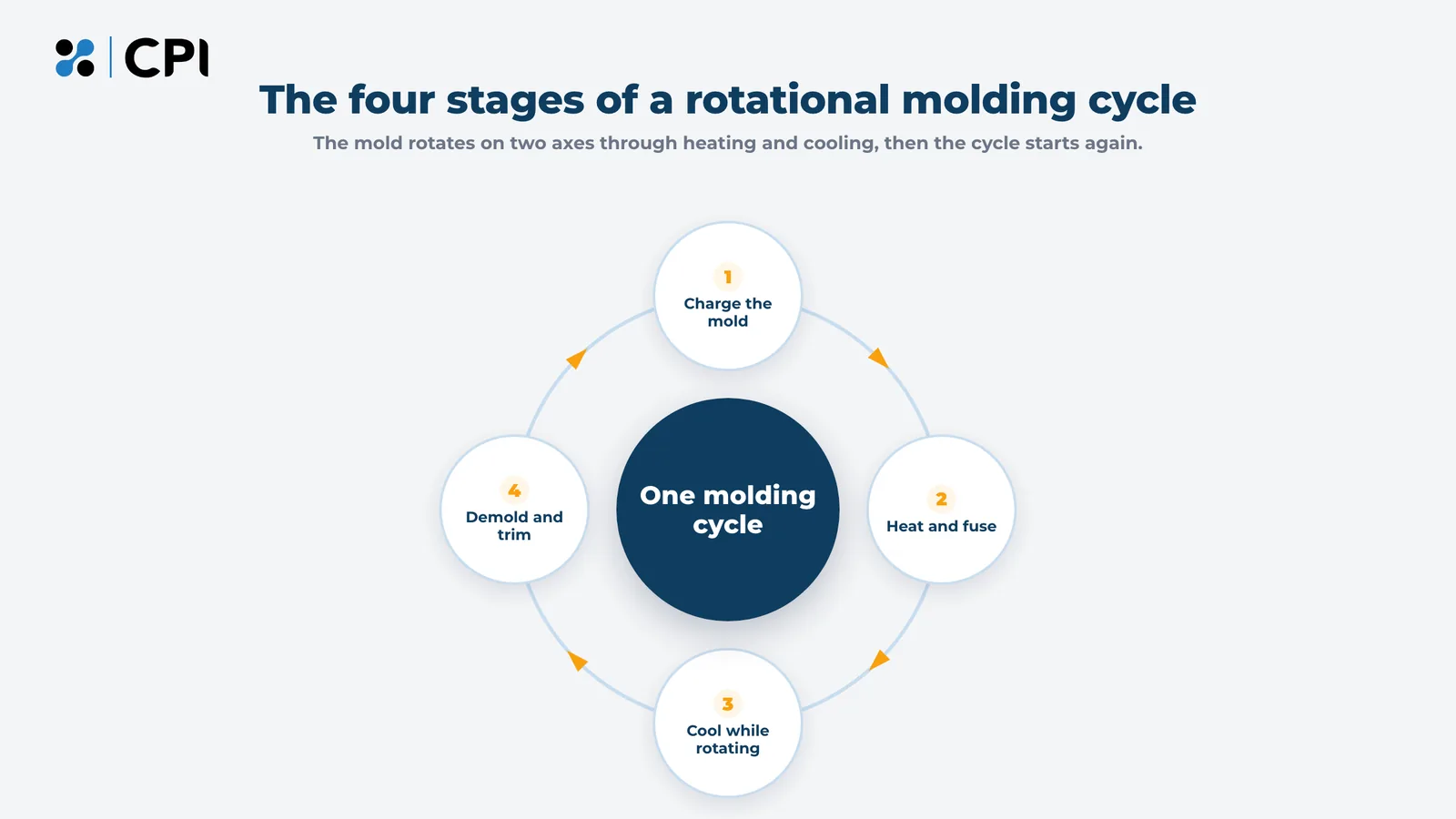
| Stage | What happens | What goes wrong |
|---|---|---|
| Charging | A weighed shot of powder and any inserts go into the mold, which is closed and clamped | A wrong shot weight makes walls too thin or too heavy |
| Heating and fusion | The rotating mold heats in an oven; powder sticks to the hot wall, melts and densifies | Too little heat leaves bubbles; too much degrades the resin |
| Cooling | Fans and sometimes water mist cool the rotating mold, and the part shrinks away from the wall | Uneven or overly fast cooling causes warpage |
| Demolding | The part comes out for trimming, drilling, hardware and inspection | A part pulled too hot distorts; poor draft causes sticking |
1. Charge the mold with a measured shot of powder
The shot weight sets the average wall thickness, because nearly all the powder ends up on the mold surface. It is roughly the part’s surface area multiplied by its nominal wall thickness and the resin’s density. Threaded inserts and other hardware are fixed to the mold wall before it closes, and an insulated drop box can add a second layer, such as a foamed core, partway through heating.
Worked example: sizing the shot for a rectangular tank
A 36 by 24 by 24 inch tank has about 4,608 square inches of surface. At a 0.25 inch wall, that is about 1,152 cubic inches of plastic. LLDPE weighs about 0.034 pounds per cubic inch, so the starting shot is roughly 39 pounds for a tank that holds close to 90 gallons. Molders then adjust the figure after measuring the first parts.
2. Heat and rotate the mold until the powder fuses and densifies
The mold rotates in the oven at low speed, usually well under 20 revolutions per minute, with oven air for polyethylene commonly between about 500 and 700 degrees Fahrenheit (260 to 370 degrees Celsius). Powder touching the hot wall turns tacky and sticks, builds up layer by layer, then melts and densifies as trapped air escapes.
Stopping too early leaves bubbles and low impact strength. Heating too long oxidizes the inner surface, which shows up as yellowing and brittleness.
Defined Term: Peak internal air temperature (PIAT)
the highest air temperature inside the mold during heating. It tracks the state of the melt more closely than oven time does, so many molders use it as the main indicator of proper cure.
Defined Term: Speed ratio
the ratio of rotation speed on the major axis to rotation speed on the minor axis. It decides how often each area of the mold passes through the powder pool, and a poor choice leaves some walls thick and others thin.
A 4:1 ratio is a common starting point for compact shapes. For each part number, log oven temperature and time, speed ratio, internal air temperature and vent condition so the cycle can be repeated.
3. Cool the mold while it keeps rotating
The mold moves to a cooling station still rotating, and fans, sometimes with water mist, cool it while the plastic crystallizes and shrinks away from the wall. Uneven cooling causes warpage because one area shrinks before another, and large flat panels are the most prone. As the air inside the mold contracts, the vent lets outside air in. A blocked vent creates a partial vacuum that distorts the soft wall.
4. Demold, trim and inspect the part
Once the part holds its shape, it comes out for secondary work: trimming openings, drilling holes (through-holes are usually machined after molding), fitting hardware, foam filling and assembly. Part weight is the fastest check on shot consistency, and a wall thickness map from ultrasonic readings on the first parts shows whether the speed ratio is putting material where the design needs it.
Why does the absence of pressure matter so much in rotational molding?
Nearly everything distinctive about rotational molding follows from the melt never being pressurized. Injection molding pushes molten plastic into a steel cavity at thousands of pounds per square inch, and blow molding inflates plastic with compressed air. Rotomolding lets the melt lie against the mold wall under its own weight.
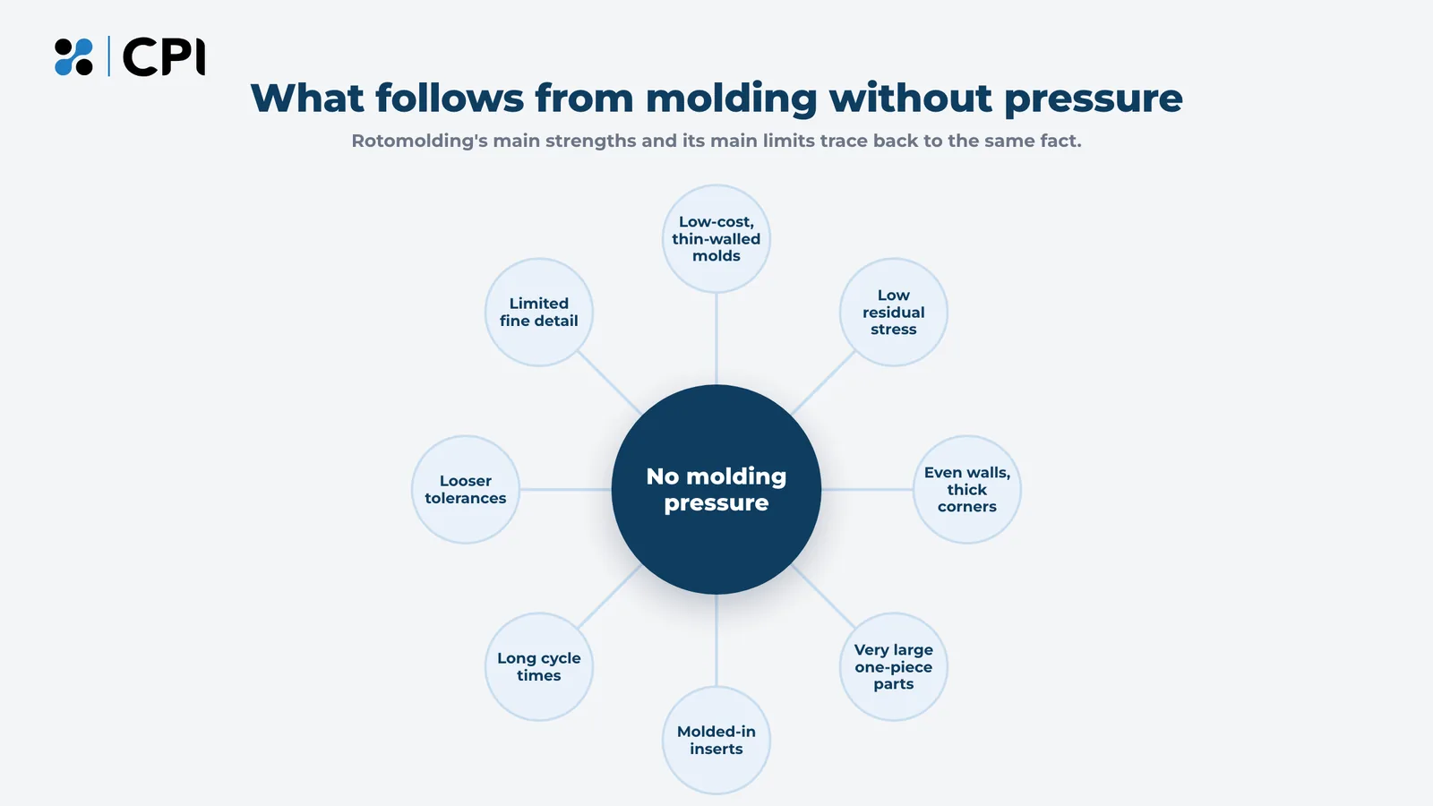
| What changes | What it means for the part |
|---|---|
| Mold construction | Thin aluminum or steel molds at a fraction of injection tooling cost |
| Residual stress | Low molded-in stress, no weld lines, and good resistance to stress cracking and impact |
| Wall thickness | Even walls, with outside corners typically at or above nominal thickness |
| Part size | Very large one-piece parts, limited mainly by oven and machine size |
| Inserts | Threaded metal inserts and hardware molded into the wall |
| Cycle time | Cycles in tens of minutes, which raises unit cost at high volume |
| Tolerance and detail | Looser tolerances and softer surface detail than pressure processes |
A buyer who picks rotomolding for its tooling cost and low stress also accepts its long cycles and looser tolerances. Process tuning improves results within those limits and leaves the limits in place.
What materials are used in rotational molding?
Polyethylene is the dominant rotational molding material, and industry estimates commonly put its share of rotomolded volume above 80 percent. It grinds cleanly into powder, tolerates long heat cycles, coats the mold evenly at low shear, and keeps its impact strength in the cold.
| Material | Why it is used | Watch for |
|---|---|---|
| Linear low-density polyethylene (LLDPE) | The default grade, with balanced stiffness, impact and stress-crack resistance and a wide processing window | Large flat walls may need ribs |
| Medium- and high-density polyethylene (MDPE, HDPE) | Higher stiffness and heat resistance | Lower impact strength as density rises |
| Crosslinked polyethylene (crosslinked PE) | High stress-crack and chemical resistance for chemical and fuel tanks | Cannot be reground or remelted |
| Polypropylene (PP) | Higher heat resistance than polyethylene | Lower impact strength in the cold |
| Nylon (polyamide) | Heat, fuel and abrasion resistance | Higher cost; needs drying |
| PVC plastisol | Soft, flexible parts molded from liquid | Liquid handling differs from powder |
| Polycarbonate, PVDF and other specialty resins | Clarity, heat or chemical performance | Narrow processing windows |
Defined Term: Crosslinked polyethylene (crosslinked PE)
a polyethylene that forms chemical bonds between polymer chains during heating, so the finished part behaves like a thermoset. It resists stress cracking and chemicals better than standard polyethylene and cannot be remelted.
Start with polyethylene and change only for a specific service condition
Begin with a rotomolding-grade LLDPE and move off it when a service condition requires it:
- Aggressive chemicals or sustained stress: crosslinked PE or a high-ESCR grade.
- High service temperatures: polypropylene or nylon.
- Fuel permeation: nylon or a multi-layer wall.
- Stiffness: a higher-density grade, or ribs and kiss-offs, which often work better.
Check the data sheet and UV package before quoting
Confirm melt flow index (rotomolding polyethylene grades commonly run about 2 to 10 grams per 10 minutes), density, low-temperature impact strength and environmental stress-crack resistance (ESCR). Outdoor parts need UV stabilizer. Precompounded color costs more than dry-blended pigment and keeps impact strength closer to the base resin’s, which matters for parts that must pass a cold impact test.
What kind of molds does rotational molding use?
Rotational molds are thin-walled shells of cast aluminum, CNC-machined aluminum or fabricated steel. Because the mold never holds pressure, it only has to keep its shape, transfer heat evenly and seal at the parting line, so it costs far less than an injection mold for a part of the same size.
| Mold type | Best for | Trade-offs |
|---|---|---|
| Cast aluminum | Complex shapes, textures, and several identical molds from one pattern | Needs a pattern first |
| CNC-machined aluminum | Precise features and a faster start with no pattern | Costly for very large molds |
| Fabricated steel | Large, simpler shapes such as tanks | Less surface detail; weld seams need finishing |
| Electroformed nickel | Very fine surface texture | Expensive and uncommon in industrial work |
Choose aluminum or steel by shape, detail and part size
Use fabricated steel for large, simple geometry, cast aluminum for complex or textured shapes and multiple copies, and machined aluminum for precise features without waiting on a pattern. Aluminum conducts heat far better than steel, so aluminum molds heat more evenly.
Place the parting line and vent before the tool is cut
Put the parting line where a small flash line does no harm, where draft is easy to provide, and away from sealing surfaces. Size the vent correctly and keep it clean.
Defined Term: Mold vent
a filtered tube through the mold wall that lets air move in and out during the cycle. It prevents blowholes at the parting line during heating and keeps the soft wall from being pulled inward during cooling.
Release agents range from sacrificial coatings reapplied often to permanent fluoropolymer coatings. Texture and lettering reproduce softer than on injection-molded parts, so size them generously.
What machines are used for rotational molding?
Rotational molding machines differ in how they move molds between loading, heating and cooling, which affects throughput and maximum part size.
| Machine type | Suited to |
|---|---|
| Carousel | Many different parts at once, with arms moving between fixed load, oven and cooling stations |
| Shuttle | Large parts, with mold carts moving between an oven and cooling stations |
| Swing arm | Mixed parts with different cycle times |
| Clamshell | Prototypes and short runs, with heating and cooling in one chamber |
| Rock and roll | Long, narrow parts such as horizontal tanks, floats and pontoons |
The arm swing diameter and oven size set the largest part a given molder can run.
What are the advantages of rotational molding?
The main advantages of rotational molding are low tooling cost, large one-piece hollow parts, even walls with strong corners, low residual stress, and molded-in inserts and double walls.
- One-piece hollow parts with no welds or bonded seams to leak or fail.
- Low tooling cost, which makes low-volume programs and design changes practical.
- Even walls with strong corners, since outside corners typically come out at or above nominal thickness.
- Low residual stress, which improves resistance to stress cracking, chemicals and impact.
- Double walls tied together at kiss-offs for stiff, insulated or foam-filled structures.
- Molded-in inserts and hardware that remove assembly steps.
- Complex geometry and layered walls, including undercuts, integrated handles, foamed cores and molded-in color.
- Economical low to mid volumes, from short prototype runs through a few thousand parts a year.
Defined Term: Kiss-off
a point where two opposing walls of a rotomolded part are molded together into a solid joint that stiffens the part.
What are the disadvantages of rotational molding?
The main disadvantages of rotational molding are long cycle times, looser tolerances, a practical floor on wall thickness, softer surface detail, a narrower material list, and a unit cost that climbs as volume rises.
| Limitation | How to work with it |
|---|---|
| Long cycle times | Run multiple molds per arm; compare other processes at high volume |
| Looser tolerances, since parts shrink 2 to 3 percent | Limit critical dimensions and machine critical features after molding |
| Wall thickness floor | Design around typical walls of 3 to 6 mm (1/8 to 1/4 inch), with about 1.5 mm as a practical minimum |
| Softer surface detail | Size text, textures and ribs generously |
| Narrower material choice | Start with polyethylene and confirm specialty resins early |
| Higher unit cost at volume | Compare total program cost, including tooling, at the real annual volume |
Rotomolding is usually the wrong process for a small housing needed by the tens of thousands, a press-fit part that must hold a few thousandths of an inch, or a thin-walled container that blow molding produces in a fraction of the time.
Have a part that has to survive the field?
CPI Products is a custom rotomolder in Port Washington, Wisconsin. Send the drawing and annual volume, and CPI will tell you directly whether rotational molding is the right process for the part.
How does rotational molding compare with blow molding, injection molding and thermoforming?
Rotational molding suits large hollow parts at low to mid volumes, blow molding suits hollow parts at high volumes, injection molding suits small detailed parts at high volumes, and thermoforming suits open shells and panels.
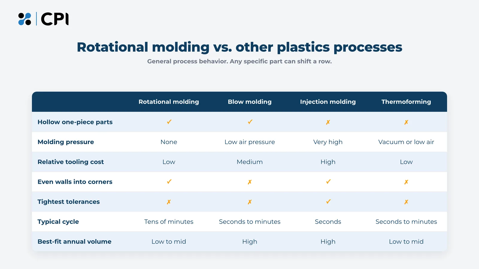
| Factor | Rotational molding | Blow molding | Injection molding | Thermoforming |
|---|---|---|---|---|
| How the part forms | Powder melts onto a heated, rotating mold | Air inflates a hot tube of plastic (the parison) against a mold | Molten plastic is injected into a steel cavity | Heated sheet is formed over a one-sided mold |
| Molding pressure | None | Low to moderate | Very high | Vacuum or low air |
| Part shape | Hollow, including double walls | Hollow, mostly closed | Solid or open, with fine features | Open shells and panels |
| Corner walls | At or above nominal | Thin where the parison stretches | Set by the steel | Thin at deep draws |
| Tooling cost | Lowest | Moderate | Highest | Low |
| Cycle time | Tens of minutes | Seconds to minutes | Seconds | Seconds to minutes |
| Typical annual volume | Prototype runs to a few thousand | Thousands to millions | Tens of thousands to millions | Hundreds to tens of thousands |
| Tolerances | Looser | Moderate | Tightest | Moderate on the mold side |
Choose rotational molding for large, hollow parts in modest numbers
It fits when the part is hollow or double-walled, annual volume runs from prototypes to a few thousand, corner strength matters, and the tooling budget is limited or the design may change.
Choose blow molding for hollow parts at high volume
Once volume reaches the tens of thousands and the shape suits a parison, the faster cycle usually outweighs the higher mold cost. Check corners and deep features, where the parison thins.
Choose injection molding for small, detailed parts in large numbers
Injection molding holds the tightest tolerances and finest detail with cycles in seconds, and its steel tooling pays back at high volume. Hollow parts have to be molded in pieces and joined.
Choose thermoforming for open shells and panels
One-sided tooling keeps cost low for covers, trays and panels, and walls thin where the sheet stretches deepest.
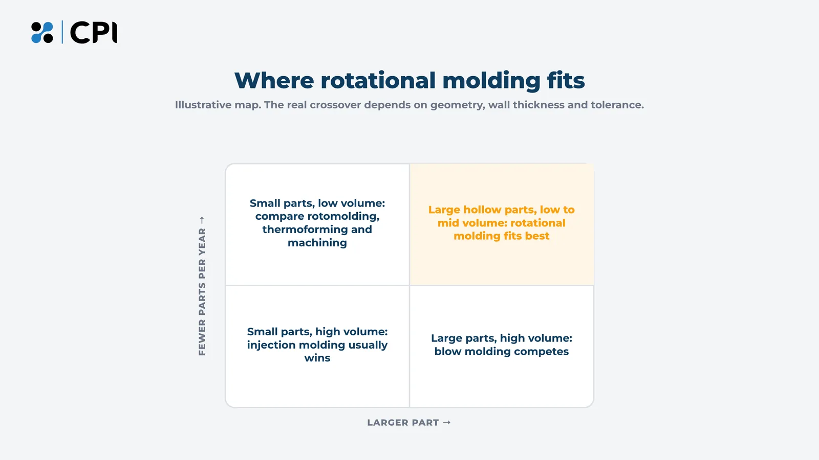
The map below is a rough guide. Comparing quotes at the real annual volume settles the close calls.
How do you design a part for rotational molding?
Designing for rotational molding comes down to one nominal wall thickness, generous radii, space between walls for powder to flow, draft where the part shrinks onto the mold, and tolerances written around 2 to 3 percent shrinkage. The figures below are common industry guidance for polyethylene. Exact values vary by resin, mold and molder.
| Design feature | Common guidance for polyethylene |
|---|---|
| Nominal wall thickness | 3 to 6 mm (about 1/8 to 1/4 inch), with a practical minimum near 1.5 mm |
| Wall thickness variation | Plan for roughly plus or minus 20 percent of nominal |
| Parallel wall spacing | At least 3 times the wall, with 5 times preferred |
| Draft angle | About 1 degree where the part shrinks away from the mold; 2 degrees or more where it shrinks onto it |
| Shrinkage | Roughly 2 to 3 percent |
| Linear tolerance | About plus or minus 1 percent of a dimension, tighter on a few critical features at added cost |
| Corners | Generous radii; avoid sharp inside corners, which run thin |
| Flat panels | Add ribs, kiss-offs or a slight crown to limit warpage |
| Holes | Usually drilled or cut after molding |
Hold one nominal wall and leave room for powder
Specify a single nominal wall and build stiffness through geometry. Rotomolding cannot reliably hold local thick or thin areas, and where it partly does, they cool unevenly and warp the part. Space parallel walls at least three wall thicknesses apart so powder can coat both sides before the gap closes.
Defined Term: Bridging
a defect where melt from two nearby walls closes a narrow gap before powder coats its bottom, leaving a void or a thin section.
Add draft and radii where the part grips the mold
Outside surfaces need about 1 degree of draft because polyethylene shrinks away from them. Surfaces the part shrinks onto, such as the inside walls of a recess or a kiss-off, need 2 degrees or more. Give every corner a radius, especially inside corners.
Write tolerances around shrinkage
List the few dimensions that matter for fit or function, give the rest a tolerance the process can hold, and design mating features to absorb variation with slotted holes, compliant fits or machining after molding.
Worked example: what shrinkage and tolerance mean on a 48-inch part
A 48-inch polyethylene part shrinks about 1.2 inches at 2.5 percent shrinkage, so the mold is cut at roughly 49.2 inches. A standard plus or minus 1 percent tolerance on that length is about plus or minus 0.48 inch. A drawing that calls out plus or minus 0.030 inch across the full length asks for something the process cannot deliver without machining or a change to how the part mates.
What causes defects in rotational molding, and how are they prevented?
Most rotational molding defects trace back to heat, venting or design. Too little heat leaves bubbles, too much degrades the resin, poor venting causes blowholes, uneven cooling causes warpage, and tight geometry causes voids.
| Defect | Usual cause | Prevention |
|---|---|---|
| Bubbles and porosity | Under-cure | Raise peak internal air temperature to the resin supplier’s range; check for moisture |
| Low impact strength | Under-cure, over-cure or poor pigment dispersion | Log internal air temperature; test impact at low temperature |
| Yellowing and a brittle inner surface | Over-cure oxidizes the melt | Shorten heating or lower oven temperature |
| Warpage | Uneven cooling, large flat panels or a hot demold | Balance cooling, add ribs or crown, and control demold temperature |
| Pinholes at the parting line | Blocked or undersized vent, or a poor mold seal | Clean and size the vent; maintain the parting line |
| Uneven wall thickness | Wrong speed ratio or uneven mold heating | Adjust the speed ratio and balance heating |
| Voids in narrow features | Walls too close together | Open spacing to 3 to 5 times the wall |
Log internal air temperature on every cycle
A probe inside the mold, read by a data logger on the arm, shows when the melt densifies and when it starts to degrade. Oven time alone shifts with mold thickness, ambient conditions and how many molds share the oven.
Test impact at low temperature and map wall thickness
The low-temperature impact test published by the Association of Rotational Molders drops a weighted dart on samples conditioned to minus 40 degrees (the same in Fahrenheit and Celsius), and both under-cured and over-cured parts tend to fail it. On first parts, map wall thickness with an ultrasonic gauge. In production, weigh every part to catch shot errors before a thin part ships.
How do you decide whether rotational molding is right for a part?
Rotational molding is right for a part when most answers below are yes. Run the checklist before the design is locked.
- Is the part hollow, double-walled or a large enclosure that would otherwise need assembly?
- Is it large enough that injection tooling would be expensive?
- Is annual volume between prototype runs and a few thousand parts?
- Can the design accept a typical nominal wall and roughly plus or minus 20 percent wall variation?
- Can critical dimensions accept rotomolding tolerances or be machined after molding?
- Is the surface detail modest enough to form without pressure?
- Is there a rotomolding-grade material, usually a polyethylene, that meets the service conditions?
Yes on questions 1 and 3 plus most of the rest makes rotomolding a strong candidate. A no on 3, 5 or 6 means comparing quotes against blow or injection molding before committing to a tool.
Have a part that has to survive the field?
Bring the checklist answers and a drawing or rough model to CPI, and work through the process decision with CPI’s engineers while the design can still change.
What is rotational molding used for?
Rotational molding is used for large hollow and double-walled parts such as tanks, housings, enclosures, liners, bins, floats, barriers and structural panels. Typical applications by industry:
| Industry | Typical rotomolded parts |
|---|---|
| Aerial lifts | Bucket liners, tool trays, covers and housings |
| Agriculture | Livestock feeders and waterers, tanks and equipment covers |
| Automotive | Specialty-vehicle fuel and fluid tanks, ducts and fender liners |
| Industrial | Process tanks, machine housings, bins, ducting and acoustic panels |
| Marine | Dock floats, buoys, fuel and water tanks, and hatches |
| Outdoor recreation | Commercial site furniture, playground components and enclosures |
| Public safety | Traffic barriers, tamper-resistant furniture and equipment cases |
| Waste management | Carts, bins, lids and collection containers |
CPI Products designs and rotomolds custom polyethylene parts for OEMs in all eight of these industries from Port Washington, Wisconsin, working from concept and prototyping through production and delivery. Parts CPI has shown publicly include livestock feeders, UV-resistant outdoor loungers, tamper-resistant furniture for a correctional institution, and bucket liners and components for aerial lifts.
Make the process decision while the design can still change
The rotomolding programs that go well share one habit: someone checked the part against the process before the geometry was frozen, setting one nominal wall, opening gaps for powder flow, writing tolerances around shrinkage and comparing the annual volume against blow or injection molding. Each check takes an hour at the drawing stage and costs far more once a mold has been cut.
Have a part that has to survive the field?
Send CPI the drawing, annual volume and service conditions for your part, and get a straight answer on whether rotational molding fits it.